Whether you’re a professional electrician or a DIY enthusiast, knowing how to measure electrical currents safely and accurately is critical. One of the best tools for this job is an electrical clamp meter. But how does a clamp meter work? This article will unravel the mysteries of this indispensable device and guide you through its proper usage for electrical measurements. Stay tuned to become an expert on clamp meters and elevate your electrical work to the next level.
What is a clamp meter?

A clamp meter, often known as a current clamp or clamp-on ammeter, is a specialized electrical test instrument with several key features:
- Primary purpose: Its main goal is to measure electrical current in a conductor without requiring physical contact or circuit disconnection. This is particularly useful for quick diagnostics and troubleshooting in both industrial and household settings.
- Clamp mechanism: The meter comes with a hinged clamp that can open and close around a wire or conductor. The clamp uses the principle of electromagnetic induction to detect and measure the current.
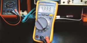
- Display: Once the clamp is in place, the reading appears on a digital or analog display. This gives you immediate insight into the current flowing through the circuit.
- Measurement buttons: These buttons allow you to choose between different types of measurements, such as:
- Alternating current (AC)
- Direct current (DC)
- Resistance
- Sometimes even voltage
By combining these components, the clamp meter provides a versatile, safe, and efficient means for electrical measurements.
Operating principles of a clamp meter
Understanding the operating principles behind a clamp meter can help you make the most of this versatile tool. Here are the fundamentals broken down:
Electromagnetic induction
- Basic concept: The core principle of a clamp meter is electromagnetic induction, a phenomenon discovered by Michael Faraday.
- Role in measurement: When electrical current flows through a conductor, it generates a magnetic field. The clamp meter’s jaws, when closed around a conductor, detect this magnetic field.
Measurement process
- Clamping: Place the jaws of the meter around a single conductor.
- Induction: The magnetic field generated by the current in the conductor induces a voltage in the sensor or transformer inside the clamp.
- Conversion: This induced voltage is then converted into an electrical current measurement displayed on the meter.
Magnetic field influence
- Sensor/transformer: The magnetic field’s strength correlates with the current flow through the conductor. The sensor or transformer inside the clamp meter is calibrated to convert this magnetic field into a precise electrical current reading.
By grasping these principles, you’ll better understand the nuances of using a clamp meter and be more capable of interpreting its measurements accurately.
Types of clamp meters

Clamp meters come in two primary types: those based on Hall Effect sensors and those based on transformer technology.
Hall effect sensors
- Working principle: These clamp meters use a Hall Effect sensor to directly measure both AC and DC currents.
- Construction: Generally more complex, featuring semiconductor materials.
Transformer-based models
- Working principle: These meters operate based on electromagnetic induction and are generally used for measuring AC currents only.
- Construction: Simpler in design, often consisting of a coil of wire that serves as the sensor.
| Feature | Hall effect sensors | Transformer-based models |
|---|---|---|
| Working principle | Hall effect | Electromagnetic induction |
| Measures | AC and DC currents | AC currents only |
| Construction complexity | More complex | Simpler |
Each type has its own set of advantages and limitations, including those that come as a multimeter with clamp meter functionalities. Hall Effect sensor-based meters are more versatile but generally more expensive, while transformer-based models are more affordable and ideal for simpler AC-only applications. Choose the one that best suits your specific measurement needs.
How to use a clamp meter: step-by-step guide

Knowing how to use clamp meter tools accurately and safely involves several steps:
- Safety precautions
- Always start by ensuring the device is in proper working condition.
- Use protective gloves and eye gear.
- Prepare the multimeter
- Turn on the device and set it to the correct measurement type (AC or DC).
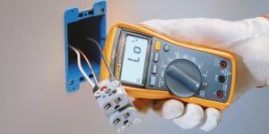
- Position the clamp
- Open the clamp jaws and encircle the conductor you wish to measure.
- Reading the display
- After positioning the clamp, the current reading will appear on the display.
- Polarity considerations
- For DC measurements, ensure you note the polarity, as indicated on the meter’s display.
- Closing the clamp
- Carefully remove the clamp from the conductor and turn off the meter.
Applications of clamp meters
Clamp meters find utility in a broad range of applications:
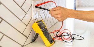
- Electrical troubleshooting: Identify overloads and trace current leakages in electrical systems.
- HVAC systems: Useful in this field for ensuring optimal power usage.
- Energy audit: Evaluate the efficiency of electrical systems to identify areas for energy savings.
Real-world examples:
- An electrician might use a clamp meter to identify which circuit is drawing excessive current, causing frequent tripping of circuit breakers.
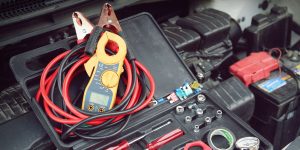
- In HVAC systems, a technician could measure the current to assess whether motors and compressors are functioning efficiently.
These real-world examples demonstrate the variety of clamp meter uses, underscoring its versatility and indispensability across different fields.
We are supported by our audience. When you purchase through links on our site, we may earn an affiliate commission at no extra cost to you.

 Best Multimeter For HVAC Technicians Reviews
 Best Automotive Multimeter Reviews
 Fluke 117 Review
 How To Test Ground On A Car With Multimeter?
 What Can You Measure With a Multimeter?
 What Type of Multimeter Do I Need?
 How To Calibrate a Multimeter?
Our newsletter
* We will never send you spam or share your email with third parties